Engineering Support
Design Considerations
— In the general introduction of this guide, it was pointed out that vibration and shock can have gross detrimental effects on the performance and reliability of a particular product. The vibration which a unit transmits to a supporting structure or the vibration which a unit feels when it is being excited by a vibrating structure can be reduced or attenuated by an isolator if properly selected. Referring to the following discussion of how an isolator functions, the design example section of this Guide contains problem solutions which use the equations and graphs presented in this section.
Vertical Vibration
In the general introduction of this guide, it was pointed out that vibration and shock can have gross detrimental effects on the performance and reliability of a particular product. The vibration which a unit transmits to a supporting structure or the vibration which a unit feels when it is being excited by a vibrating structure can be reduced or attenuated by an isolator if properly selected. Referring to the following discussion of how an isolator functions, the design example section of this Guide contains problem solutions which use the equations and graphs presented in this section.
![]()

Fig. 4: Schematic of the simplest form of an isolator, a spring, K, and a viscous damper, C, supporting the equipment mass, M.
The function of an isolator may be best understood by first reducing it to its simplest form, as illustrated in Figure 4. The system of Figure 4 includes a rigid mass M supported by a spring K and constrained by guides to move only in vertical translation without rotation about a vertical axis. A damper C is arranged in parallel with the spring between the support and the mass. The mounted equipment is simulated by the mass while the spring and damper taken together simulate the elasticity and damping of the conventional isolator. The system shown in Figure 4 is said to be a single-degree-of-freedom system because its configuration at any time may be specified by a single coordinate: e.f., by the height of the mass M with respect to the fixed support.
Isolation is attained primarily by maintaining the proper relationship between the disturbing frequency and the system's natural frequency. The characteristics of the isolator include its natural frequency, or more properly, the natural frequency of the system consisting of isolator and mounted equipment. In general, a system has a natural frequency for each degree of freedom: the single-degree-of-freedom system illustrated in Figure 4 thus has one natural frequency. The expression for the damped natural frequency of the system illustrated in Figure 4, expressed in cycles per second, is:
Eq. 6

A critical damped system returns without oscillation to equilibrium if displaced; it has no natural frequency of oscillation, as indicated by the substitution of C=Cc in Equation 6.
In most circumstances the value of the damping coefficient is relatively small. The influence of damping on the natural frequency may then be neglected. Setting the damping coefficient C equal to zero, the system becomes an undamped single-degree-of-freedom system, and the undamped natural frequency given by:
Eq. 2

This expression is sufficiently accurate for calculating the actual natural frequency in most instances.
The concept of static deflection often is used to define the characteristics of an isolator. Static deflection is the deflection of the isolator under the static or deadweight load of the mounted equipment. Referring to Equation 2 and substituting in/sec2, the following expression is obtained for natural frequency in terms of static deflection:
Eq, 4


Figure 5: Relation of natural frequency and static deflection of a linear, single-degree-of-freedom system.
A graphic portrayal of Equation 4 is given in Figure 5. It thus appears possible to determine the natural frequency of a single-degree-of-freedom system by measuring only the static deflection. This is true with certain qualification. First, the spring must be linear - its force vs. deflection curve must be a straight line. Second, the resilient material must have the same type of elasticity under both static and dynamic conditions.
Metallic springs generally meet this latter requirement, but many organic materials used in isolators do not. The dynamic modulus of elasticity of these materials is higher than the static modulus, the natural frequency of the isolator is thus somewhat greater than that calculated on the basis of static deflection alone.
Dynamic stiffness may be obtained indirectly by determining the natural frequency when the isolator is vibrated with a known load and calculating the dynamic stiffness from Equation 2. The various organic materials have certain peculiarities with respect to dynamic stiffness which will be discussed later in connection with the specific materials.
Effectiveness of isolators in reducing vibration is indicated by the transmissibility of the system. Figure 6 illustrates a typical transmissibility curve for an equipment of weight W supported on an isolator with stiffness K and damping coefficient C which is subjected to a vibration disturbance of frequency fd. When the system is excited at its natural frequency, the system will be in resonance and the disturbance forces will be amplified rather than reduced. Therefore, it is very desirable to select the proper isolator so that its natural frequency will be excited as little as possible in service and will not coincide with any critical frequencies of the equipment.
Referring to Figure 6, it can be seen that when the ratio of the disturbing frequency fd over the natural frequency fn is less than or 1.4, the transmissibility is greater than 1, or the equipment experiences amplification of the input. Simply expressed, when:

theoretically, isolation begins when:

Also it can be seen that when:

the mounted unit is said to be isolated; i.e., the output X0 is less than input Xi.
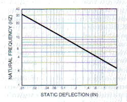
Figure 6: Typical transmissibility curve for an isolated system where fd = disturbance frequency and fn = isolation system natural frequency.
Damping
The majority of isolators possess damping in varying degrees. A convenient reference illustrating damping factor C/Cc for various materials is shown in Table 1. Damping as advantageous when the mounted system is operating at or near its natural frequency because it helps to reduce transmissibility. For example, consider an internal combustion engine mounted on steel springs which possess very little damping (see Table 1). Upon start up of the engine and as the engine RPM increases, the disturbing frequency of the engine will at some point correspond with the natural frequency of the spring-mass system. With light damping, the buildup of forces from the engine to the support will be very large; that is, transmissibility will be very high. If the idle RPM of the engine falls in the range of the natural frequency of the spring-mass system, serious damage may result to the engine or to the support chassis. If, on the other hand, the designer selects an elastomeric isolator which possesses a higher degree of damping, amplification at resonance would be much less.
| Material | Approx. Damping Factor C/Cc |
Tmax (approx) |
| Steel Spring | 0.005 | 100 |
| Elastomers: | ||
| Natural Rubber | 0.05 | 10 |
| Neoprene | 0.05 | 10 |
| Butyl | 0.12 | 4.0 |
| Barry Hi Damp | 0.15 | 3.5 |
| Barry LT | 0.11 | 4.5 |
| Barry Universal | 0.08 | 6.0 |
| Friction Damped Springs | 0.33 | 1.5 |
| Metal Mesh | 0.12 | 4.0 |
| Air Damping | 0.17 | 3.0 |
| Felt and Cork | 0.06 | 8.0 |
The relationship between a highly damped and a lightly damped system is illustrated in Figure 8. This figure shows that as damping is increased, isolation efficiency is somewhat reduced in the isolation region. While high values of damping cause significant reduction of transmissibility at resonance, its effect in the isolation region is only a small increase transmissibility.
A family of curves which relate to fn, fd, transmissibility and damping are shown in Figure 8. This family of curves was derived by use of Equation 10.
Horizontal Vibration
When an isolation system is excited horizontally, two natural frequencies result if the center of gravity of the unit is not in line with the elastic center of the isolators. A typical transmissibility curve illustrating this horizontal vibration output is illustrated in Figure 9. The two natural frequencies which are involved include a lower mode wherein the equipment rocks about a point well below the elastic center of the isolators and a higher mode where the equipment oscillates abut a point in the vicinity of the center of gravity. Two other natural frequencies will occur if the equipment is rotated 90 degrees in the horizontal plane with respect to the exciting force.
Figure 10 can be used to determine the approximate frequencies of these modes as a function of spring stiffness and equipment dimensions. These curves assume that the equipment is solid, of uniform mass, and that the isolators are attached at the extreme corners. Under horizontal excitation the equipment may be made to translate only by lining up the center of gravity of the equipment with the elastic center of the isolators instad of installing the isolators at the bottom corners of the equipment. In this case, Figure 10 may be applied by letting H/W = 0, which results in only one mode of vibration, that of translation. A second mode can only be excited by torsional excitation.
Structure-Borne Noise
The demand on equipment today is to maximize its output which generally requires faster operation and more complex mechanical motions. As a result, noise is sometimes generated high frequency disturbances are excited because the moving components within the equipment impose vibratory inputs to the internal structures. These vibrations are amplified and structure-borne noise is encountered. Complete equipment bolted to their support foundations also cause similar noisy conditions.
An effective and low cost means of alleviating structure-borne noise problems is to physically separate the solid structures and interpose a resilient material between them. In this manner a mechanical attachment is provided but the resilient media prevents the vibration forces from being transmitted and structure-borne noise is substantially reduced.
Elastomeric materials are generally best suited for structure-borne noise reduction. They exhibit the desirable characteristics of shape flexibility and inherent damping to avoid spring-like response which might produce violent resonances at critical frequencies. They afford high frequency isolation. Many isolators suitable for attenuation of structure-borne noise problems are available from Barry.
Shock
Shock is normally classified as a transient phenomenon, while a typical vibration input is classified as a steady-state phenomenon. A shock input pulse is normally described by its peak amplitude A expressed in g's, by its duration t normally expressed in milliseconds, and its overall shape, which can take such forms as half-sine, triangular, (initial peak sawtooth, symmetrical and terminal peak sawtooth), versed sine, rectangular, and the form most likely to occur in nature, a more or less random shaped complex waveform force and acceleration impulse as shown in Figure 11.
Since there are many types of shock pulses encountered in nature, there are many types of shock tests specified for testing a piece of equipment. The different shock tests are normally associated with the environment that the equipment will encounter during its lifetime. Equipment installed in aircraft is normally tested on a free-fall shock machine which will generate either a half-sine or terminal peak sawtooth form. A typical test is an 11-millisecond half-sine waveform with a peak acceleration of 15 g's. For components in some areas of missiles where large shock pulses will be felt due to explosive separation of stages, a 6-millisecond sawtooth at 100 g's may be specified. If a piece of equipment is going on board a Navy vessel, the normal test will be the hammer blow specified in MIL-S-901, which exhibits a velocity shock of approximately 120 in./sec. Shipping containers are normally tested by dropping the container on a concrete floor, or by suspending it by some suitable support mechanism and letting it swing against a concrete abutment. Other tests pertaining to shipment are edge and corner drops from various drop heights. All of these tests mentioned attempt to simulate the shock pulse which will be encountered in the normal environment of the equipment. These are generally called out by the specific contractual requirements either in specifications or in a work requirement.
The isolation of shock inputs is considerably different from that of a vibration input. The shock isolator is characterized as a storage device wherein the input energy, usually with a very steep wave front, is instantaneously absorbed by the isolator. This energy is stored in the isolator and released at the natural frequency of the spring-mass system.
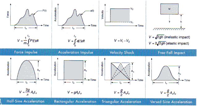
Figure 11: Idealized forms of shock excitation and the velocity change, V, associated with each shock pulse
The most common procedure for predicting shock isolation is a mathematical approach utilizing equations in Figure 11, for determining the velocity, and Equation 13, for calculating transmitted accelerations.
Another means is through the use of shock transmissibility curves. Shock transmissibility curves are not included in this Guide but are included in a technical paper published by Barry Controls title "Passive Shock Isolation." Please call 1-800-BARRY MA for a copy of this paper.
These two methods are valid for solving shock problems provided that the shock pulse is thoroughly defined, and that the isolation system responds in its linear region.
Nonlinear Isolators
The preceding discussion of vibration and shock isolation presumes that the the isolator is linear, the force-direction curve for the isolator is a straight line. This simplified analysis is entirely adequate for many purposes. In the isolation of steady-state vibration, displacement amplitude is usually small, and nonlinearity of the isolator tends to be unimportant except where deflection resulting from the static load is relatively great. In the isolation of shock, nonlinearity tends to be more important because large deflections prevail. The degree of isolation may then be substantially affected by the ability, or lack thereof, of the isolator to accommodate the required deflection.
In many applications of shock isolation, sufficient space is not available to allow for full travel of a linear isolator. Therefore, a nonlinear isolator is necessary. There are two types of isolators that can be designed to help solve the problem of insufficient space.
The first solution is to make an isolator that gets stiffer as deflection increases. This will limit the amount of motion, but will increase the G level imparted on the equipment.
The second is to use an isolator that is stiff at small deflection, but gets softer at higher deflections. This is referred to as a buckling isolator, and is shown in Figure 12. This allows the isolator to store more energy in the same amount of deflection. (A shock isolator is basically an energy storage device; it stores high g-level, short-duration shock and releases them as low g-level, longer-duration shocks.)
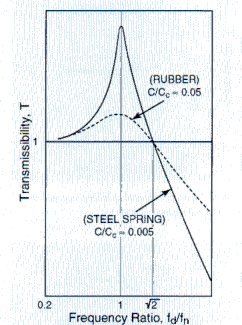
Figure 7: Typical transmissibility curves for highly and lightly damped systems.
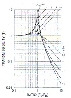
Figure 8: Family of transmissibility curves for a single degree of freedom system.
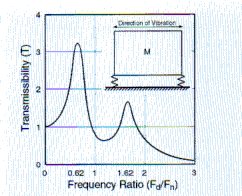
Figure 9: Typical transmissibility curve for horizontal vibration inputs
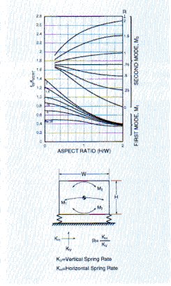
Figure 10: Horizontal natural frequencies of a homogeneous solid mounted on linear, undamped springs at edge of mass.
Contact Us
The personal data collected are processed, the responsibility of which is HUTCHINSON AEROSPACE & INDUSTRY INC. company, in order to respond to your request for information and/or for the purpose of commercial prospecting. Mandatory fields to be completed are marked with an asterisk. The legal basis for the processing is your consent, which you may withdraw at any time, without prejudice to previous processing operations. Personal data are reserved for the use of the HUTCHINSON group and may only be transmitted to companies of the HUTCHINSON group and/or commercial partners for commercial purposes, if you have expressly consented to this.
In accordance with the regulation relating to personal data (GDPR), you have the right of access, rectification and erasure of your personal data, as well as the right of opposition to their processing. You may request the disclosure of your personal data and you have the right to define guidelines for the treatment of your personal data after your death. You can also request the portability of your data as well as the limitation of their processing, and/or file a complaint to your local authority.
You can exercise your rights and ask us about the processing of your personal data by contacting us at the following email address: [email protected]
To find out more read our Privacy and Cookies Policy.
