Engineering Support
Design Examples
— This section deals with the selection and application of vibration and shock isolators. For the proper selections of isolators, it is desirable to obtain, where possible, pertinent information relating to the equipment, input and output requirements, and the general environment. Examples of the type of information or data required are:
Relating to the equipment:
- Weight
- Dimensions
- CG location
- Number and location of isolators
- Available space for isolator
- Fragility level of the equipment
Relating to the dynamic inputs and outputs:
- Level of vibration
- Level of shock
- Space limitations
Relating to general environment:
- Temperature
- Humidity
- Salt spray
- Corrosive atmosphere
- Altitude
All of the above information is not always readily available nor is it always completely required in some applications. This will be further clarified in the following problem examples.
Example 1 - Vertical Vibrations
A metal tumbling drum directly driven by a 1080 RPM motor is causing vibration disturbance to the floor on which it is mounted the drum, motor, and support base weighs 400 pounds. There are 4 mounting points for the isolators. The required isolation is 80%.
- Determine fn of isolators required by using mathematical methods.
- Determine static deflection of isolators by using (a) mathematical methods and (b) the static deflection vs. natural frequency curve. (Fig. 5)

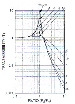
- Determine damping factor C/Cc to limit transmissibility at resonance to 10 by using (a) mathematical methods and (b) the transmissibility curve shown below.

- Determine the resilient media which could be used in the isolator selected to provide the C/Cc required.
- Determine the proper isolator to use for this application.
Solution:
Known Facts: W = 400 lb
Weight per mounting point = 400/4 = 100 lb
Isolation required = 80%
i.e. transmissibility = 0.20
Disturbing frequency, fd = 1080 RPM
1. Using this equation

2a. To find static deflection using mathematical approach use this equation:

2b. To find static deflection using static deflection-natural frequency curve (Fig. 5). The intersection of fn of 7.35 and the solid diagonal line yields a Ds of approximately 0.18 inches.
3a. To find C/Cc for a transmissibility of 10 by mathematic approach use

Solving for C/Cc:

3b. To find C/Cc for a T of 10 by use of the transmissibility curve shown above. This curve shows that for a transmissibility of 10, C/Cc = 0.05
4a. To find the correct resilient media which exhibits a C/Cc = 0.05 refer to Table 1 in Design Considerations. It can be seen that natural rubber or neoprene would be the proper selection.
5a. An isolator which best fits the above solved parameters is Barry Part No. 633A-100. Refer to the product page to confirm that this product meets all of the above needs.
Example 2 - Vertical and Horizontal Vibration
An electronic transmitter which weighs 100 lbs., and has a hight of 15", a width of 20" and a length of 30" is to be mounted in a ground vehicle which imparts both vertical and horizontal vibratory inputs to the equipment. Since rough terrain is to be encountered a captive isolator is required. Four mounting points, one at each corner, are provided. It has been determined that the first critical frequency of the equipment is such that an isolator with a 25 Hz vertical natural frequency would be satisfactory. Select an appropriate isolator and determine the approximate horizontal rocking modes in the direction of the short axis of the equipment which would be excited.
Solution:
1. For vertical natural frequency: Load per isolator = 100/4 = 25 lb.
Referring to a Barry isolator series designed for the rigors of vehicular applications, the 5200 series is suitable. From the load rating table in the product information section (18-30 pounds capacity for vehicular applications) would handle the 25 pound load.
Using the lode vs natural frequency plots on the 5200 Performance Data Sheet, the intersection of the 5220 curve for the 25 pounds load yields an fn of 24 Hz.
Solution continued...
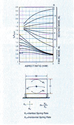
2. For horizontal rocking modes: the dynamic stiffness ratio of horizontal to vertical = 0.6 for the 5200 series. Referring to the figure below and assuming that mass is homogeneous and isolator are at extreme corners, the following is found:


Fig. 10
From the curves in Figure 10, the ratios of fn/fVERT for first mode M1 is 0.7 and for second mode, M2, is 1.7.
fn, 1st mode = 24 x 0.7 = 16.9 Hz
fn, 2nd mode = 24 x 1.7 = 40.8 Hz
It is seen that this procedure lends a ready solution to determining the horizontal rocking modes based on the assumptions made. This solution is not exact but is generally satisfactory for practical purposes.
Example 3 - Shock
An electronic equipment is to be subjected to 15G, 11 millisecond half-sine shock input. The equipment is mounted on a 10 Hz natural frequency isolation system. Determine maximum shock transmission and isolator deflection.
Solution:

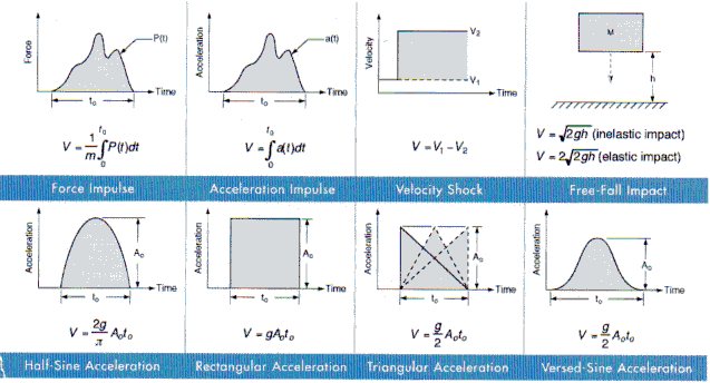
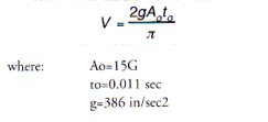
1. From Figure 11, the equation for shock velocity change for a half-sine pulse is


using this equation:  , the maximum shock transmission is:

using this equation: 
the isolator deflection required to attenuate this shock:

This example could also be done in the "reverse" direction. If one knew the desired output, 6.6G's one could calculate the required natural frequency, 10 Hz, to attenuate the input shock.
In either case, the deflection is calculated last, and used t to determine 1) if the allowable sway space is sufficient to accommodate the required deflection, and 2) if the selected isolator has enough linear deflection capability to withstand the shock.
Contact Us
The personal data collected are processed, the responsibility of which is HUTCHINSON AEROSPACE & INDUSTRY INC. company, in order to respond to your request for information and/or for the purpose of commercial prospecting. Mandatory fields to be completed are marked with an asterisk. The legal basis for the processing is your consent, which you may withdraw at any time, without prejudice to previous processing operations. Personal data are reserved for the use of the HUTCHINSON group and may only be transmitted to companies of the HUTCHINSON group and/or commercial partners for commercial purposes, if you have expressly consented to this.
In accordance with the regulation relating to personal data (GDPR), you have the right of access, rectification and erasure of your personal data, as well as the right of opposition to their processing. You may request the disclosure of your personal data and you have the right to define guidelines for the treatment of your personal data after your death. You can also request the portability of your data as well as the limitation of their processing, and/or file a complaint to your local authority.
You can exercise your rights and ask us about the processing of your personal data by contacting us at the following email address: [email protected]
To find out more read our Privacy and Cookies Policy.
